


Clock timing helps electronic circuits work in the right order. Oscillators and clock generators both create timing signals, but they serve different needs. An oscillator produces a single clock signal, while a clock generator generates and distributes multiple clocks from a reference source. This article provides information on their functions, differences, uses, performance factors, and selection criteria.

Oscillators and Clock Generators Overview
An oscillator is an electronic circuit or component that generates a repeating waveform. This waveform is used as a timing reference for circuits such as microcontrollers, sensors, communication modules, and actual clocks.
A clock generator is a timing device that produces clock signals for digital systems. It starts with a reference source, such as a crystal or oscillator, and then generates one or more output clocks for different devices or subsystems.
The relationship is simple: an oscillator can act as the original timing source, while a clock generator can use that source to create and distribute additional clocks.
How Oscillators and Clock Generators Work
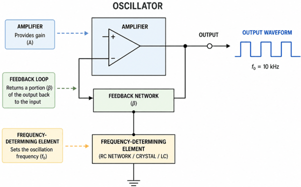
An oscillator produces a continuous repeating signal without needing an external clock input. Most oscillators use three main elements: an active circuit, a feedback path, and a frequency-determining component.
The active circuit provides gain. The feedback path returns part of the output signal back to the input. The frequency-determining component controls the oscillation frequency. Depending on the design, this element may be a quartz crystal, MEMS resonator, ceramic resonator, RC network, or LC resonant circuit.
| Oscillator Type | How It Works | Typical Use |
|---|---|---|
| Crystal oscillator | Uses a quartz crystal for accurate frequency control | MCUs, USB, Ethernet, communication circuits, timing references |
| MEMS oscillator | Uses a silicon MEMS resonator with integrated oscillator circuitry | IoT devices, wearables, automotive electronics, industrial systems |
| Ceramic resonator oscillator | Uses a ceramic resonator for moderate accuracy at lower cost | Remote controls, toys, appliances, simple controller boards |
| RC oscillator | Uses a resistor-capacitor network to set frequency | Internal MCU clocks, watchdog timers, simple low-cost timing |
| LC oscillator | Uses an inductor-capacitor resonant circuit | RF circuits, wireless systems, signal generators, tunable frequency circuits |
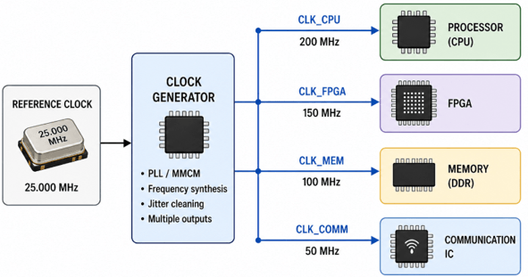
A clock generator receives a reference clock from a crystal, oscillator, or external timing source. It then processes that reference to create the clock outputs required by the system.
Many clock generators use a PLL, or phase-locked loop, to multiply, divide, or adjust frequency. For example, a single reference clock may be used to generate multiple output frequencies for a processor, FPGA, memory device, or communication interface.
Clock generators may also include output buffers to drive multiple devices and support different signal formats such as CMOS, LVDS, LVPECL, or HCSL. Their main purpose is system-level clock management. Instead of using several separate oscillators, a designer can use one reference source and a clock generator to supply the required clocks across the board.
Oscillators vs Clock Generators: Main Differences
An oscillator and a clock generator are both used for timing, but they serve different design needs. An oscillator is used as a simple standalone clock source, while a clock generator is used when a system needs multiple clock signals, frequency conversion, or clock coordination.
| Feature | Oscillator | Clock Generator |
|---|---|---|
| Main purpose | Produces a stable periodic clock signal | Creates, adjusts, and distributes system clock signals |
| Typical input | Works by itself and does not need an external clock input | Needs a reference signal from a crystal, oscillator, or other clock source |
| Output count | Provides one clock output | Can provide multiple clock outputs |
| Frequency flexibility | Often fixed or available in limited frequency options | Can generate different frequencies from one reference source |
| Circuit complexity | Simpler device with fewer timing functions | More complex because it may include PLLs, dividers, buffers, or output controls |
| Clock distribution | Mainly supplies one local timing signal | Can distribute clocks to several ICs or system sections |
| Synchronization ability | Limited synchronization control | Better for coordinating multiple system clocks |
| Common use | Simple embedded boards, sensor modules, consumer electronics, and basic RF circuits | FPGA boards, processor systems, networking equipment, data converters, and high-speed interfaces |
| Cost | Lower | Higher |
Crystal vs Oscillator vs Clock Generator vs Clock Buffer vs PLL
A crystal, oscillator, clock generator, clock buffer, and PLL are related timing components, but they are not the same. A crystal is a passive resonator, an oscillator is an active clock source, a clock generator creates multiple clock signals, a clock buffer distributes an existing clock, and a PLL controls or synthesizes frequency using feedback.
| Device | Main Function | Typical Input | Typical Output | Best Use |
|---|---|---|---|---|
| Crystal | Provides a passive frequency reference | Needs an oscillator circuit to operate | Does not directly output a logic-level clock by itself | Low-cost frequency reference for MCUs, RTCs, and oscillator circuits |
| Oscillator | Generates a complete clock signal | Works from power only because the resonator and oscillator circuit are inside the package | One fixed clock output, usually CMOS, LVDS, LVPECL, or similar | Basic timing source for simple circuits |
| Clock generator | Creates one or more system clocks from a reference | Crystal, oscillator, or external reference clock | Multiple clock outputs, often at different frequencies | Multi-clock systems such as FPGA, processor, networking, and communication boards |
| Clock buffer | Copies and distributes an existing clock | Existing clock signal | Multiple copies of the same or related clock signal | Clock fanout, signal distribution, and driving several ICs |
| PLL | Locks, multiplies, divides, or cleans a frequency | Reference clock or crystal-based signal | Controlled output frequency related to the reference | Frequency synthesis, jitter reduction, synchronization, and clock recovery |
Frequency Accuracy, Stability, and Jitter Comparison
Frequency Accuracy
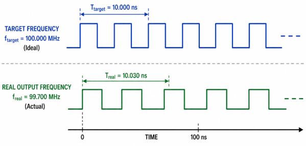
Frequency accuracy describes how close the output frequency is to the intended value. A crystal oscillator provides better accuracy than an RC oscillator. A clock generator can also provide accurate outputs when it is driven by a stable reference source.
Accuracy is required in communication interfaces, USB, Ethernet, wireless systems, and timing-sensitive embedded designs.
Stability Over Temperature
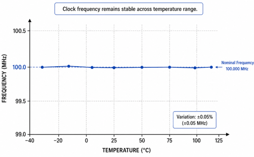
Frequency stability describes how much the clock's frequency changes with temperature, voltage, and aging. Crystal-based timing sources offer greater stability than simple RC-based sources.
For applications exposed to wide temperature ranges, designers may use more stable options such as TCXOs or carefully specified reference clocks.
Jitter and Phase Noise
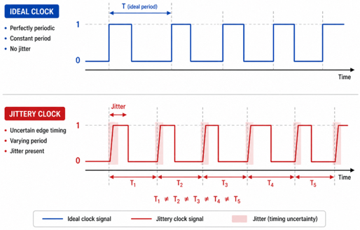
Jitter is the short-term variation in the timing of clock edges. Phase noise describes unwanted frequency noise around the clock signal. Both are required in high-speed, high-precision systems.
Excessive jitter can reduce timing margin in communication links and lower signal quality in ADCs and DACs. For this reason, high-speed interfaces, RF circuits, and data converter systems often require low-jitter timing devices.
Output Signal Quality
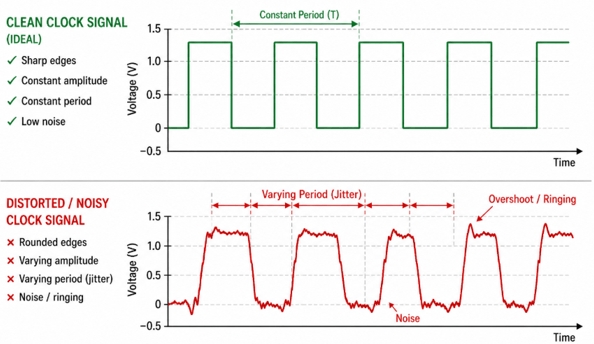
Output signal quality includes duty cycle, rise time, fall time, voltage level, and waveform shape. Poor signal quality can lead to unreliable switching, EMI issues, or timing errors.
Clock generators often offer more output format options than simple oscillators, making them useful in systems with varying clock input requirements.
When to Use an Oscillator?
Use an oscillator when the circuit needs one stable clock signal, fixed frequency operation, low component count, and simple local timing. It is usually the better option for small embedded boards, sensor modules, consumer products, and basic communication circuits.
| Use Case | Why an Oscillator Fits | Example Devices |
|---|---|---|
| Microcontroller and embedded boards | Provides one stable system clock for MCU operation, timers, and basic control tasks | ECS ECS-2520MV series; SiTime SiT8008B |
| Sensor modules and IoT devices | Supports compact, low-power timing for sampling, MCU control, and wireless communication | ECS-2520MV-250-BN-TR |
| Low-cost consumer electronics | Offers fixed-frequency timing with simple design and lower component cost | Abracon ASV series |
| Basic RF and communication circuits | Provides a local frequency reference when multiple synchronized outputs are not required | TXC 7W series; SiTime SiT8008B |
When to Use a Clock Generator?
Use a clock generator when the system needs multiple clock outputs, different frequencies, low-jitter timing, or coordinated clock distribution. It is better suited for processor boards, FPGAs, networking equipment, high-speed interfaces, and data converter systems.
| Use Case | Why a Clock Generator Fits | Example Devices |
|---|---|---|
| FPGA and processor boards | Generates different clocks for processors, FPGAs, memory, and communication interfaces from one reference | Skyworks/Silicon Labs Si5341; Renesas 9FGV1006 |
| PCIe, USB, Ethernet, and SerDes systems | Provides low-jitter timing for high-speed interfaces where poor clock quality can cause data errors | Renesas 9FGV1002; Renesas 9FGV1006 |
| Networking and communication equipment | Supports coordinated timing for PHYs, SerDes channels, processors, and system clock trees | Skyworks/Silicon Labs Si5340; Si5341 |
| ADC, DAC, audio, and video systems | Reduces sampling error and keeps related clocks aligned for signal-chain performance | Texas Instruments LMK04828; Skyworks/Silicon Labs Si5341 |
How to Select the Timing Devices
| Timing Need | Better Choice | Why |
|---|---|---|
| One basic clock signal | Oscillator | Provides simple, stable timing without clock-management functions |
| Several clock outputs | Clock generator | Creates and distributes multiple clocks from one reference |
| Lower circuit complexity | Oscillator | Needs fewer parts and less control circuitry |
| Different clock frequencies | Clock generator | Generates multiple frequencies for different system sections |
| Simple local timing | Oscillator | Works well when timing is needed in only one part of the circuit |
| Coordinated system timing | Clock generator | Helps keep several clock signals aligned and controlled |
| Driving several ICs with the same clock | Clock buffer | Distributes one clock to multiple loads |
| Frequency multiplication or synchronization | PLL | Multiplies, divides, locks, or cleans clock signals |
Required Frequency
Choose a timing device that supports the target operating frequency and the required frequency accuracy. A fixed-frequency design may use a standard oscillator, while a design with several required frequencies may need a clock generator.
Number of Clock Outputs
If the circuit only needs one clock output, a single oscillator may be enough. If several ICs need separate or coordinated clocks, a clock generator or clock buffer may be more suitable.
Jitter Tolerance
Jitter is the small timing variation in a clock signal. Low-jitter timing is important in high-speed interfaces, RF systems, ADCs, DACs, and communication circuits because clock noise can affect signal quality and data reliability.
Frequency Stability
Frequency stability describes how well the clock maintains its frequency across temperature, voltage, and aging changes. Higher stability is required in systems that need accurate timing over long operation periods or changing environmental conditions.
Power Consumption
Power consumption is important in battery-powered, portable, and always-on devices. A simple oscillator is often more power-efficient, while a clock generator may consume more power because it includes extra functions such as PLLs, dividers, and multiple output drivers.
Board Space
Board space matters in compact products such as IoT devices, wearables, sensor modules, and portable electronics. Integrated oscillators, MEMS oscillators, or clock generators can reduce component count compared with using several separate timing parts.
Vibration and Shock Tolerance
Vibration and shock tolerance should be considered in automotive systems, industrial equipment, drones, robotics, transportation electronics, and other products exposed to movement or mechanical stress.
Common Problems Caused by Poor Clock Selection
System Instability
System instability can occur when the clock frequency or stability does not meet the circuit’s timing requirements. The circuit may not run consistently if the clock is too inaccurate, unstable, or poorly matched.
Communication Errors
Communication errors can occur when the clock timing is inaccurate or noisy. If the timing signal is not clean enough, data transfer may become unreliable.
Data Corruption
Data corruption can happen when data is captured at the wrong time. This may occur if the clock edge arrives too early, too late, or exhibits excessive timing variation.
ADC and DAC Performance Loss
ADC and DAC performance can drop when clock jitter reduces signal quality. A noisy or unstable clock can affect the accuracy of signal conversion.
Timing Violations
Timing violations occur when clock edges arrive too early or too late. This can prevent parts of the circuit from meeting their required timing limits.
EMI Issues
EMI issues can happen when clock routing or edge rates are poorly controlled. Fast or poorly routed clock signals may create unwanted electrical noise.
Clock Skew
Clock skew happens when distributed clocks arrive at different times. This becomes a problem when several parts of a circuit must work from related clock signals.
Startup Failure
Startup failure can happen when devices do not receive a valid clock when needed. If the clock is missing, late, or unstable during startup, the circuit may not begin operating correctly.
Frequently Asked Questions [FAQ]
Q1. What is the main difference between an oscillator and a clock generator?
An oscillator generates a single timing signal. A clock generator uses a reference source to create, adjust, and distribute one or more clock signals across a system.
Q2. Why does a clock generator need a reference clock?
A clock generator starts with a crystal, an oscillator, or an external clock. It uses that reference to create the frequencies needed by different parts of the circuit.
Q3. How does jitter affect clock selection?
Jitter is a small timing variation in clock edges. Too much jitter can cause data errors, reduce timing margin, and lower ADC or DAC signal quality.
Q4. Is a clock generator always more accurate than an oscillator?
No. A clock generator depends on the quality of its reference clock. A stable reference can produce accurate outputs, but a poor reference can still cause timing problems.
Q5. What does a PLL do in a clock generator?
A PLL helps multiply, divide, adjust, or synchronize clock frequencies. This allows a single reference clock to support multiple timing needs.
Q6. What problems can poor clock selection cause?
Poor clock selection can cause instability, communication errors, data corruption, timing violations, EMI issues, clock skew, startup failure, and ADC/DAC performance loss.
Q7. How do you choose between an oscillator, clock generator, clock buffer, and PLL?
Use an oscillator for a basic clock, a clock generator for multiple clocks, a clock buffer for distributing an existing clock, and a PLL for frequency control or synchronization.